Sensors
Hardware - Understanding Sensor Technology
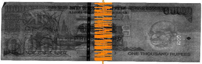
Various images seen with different wavelength lights.
Banknotes contain various security features that can only be detected under specific wavelengths of light. Banknote counters emit three types of light and analyze the reflected or transmitted images to determine — within 0.001 seconds — whether a note is genuine or counterfeit.
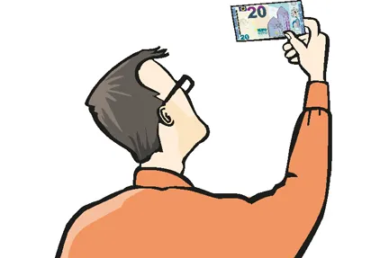
Visible Light Sensor
The Visible Light Sensor captures banknote images just as the human eye sees them. These images are typically used to determine the denomination, capture the serial number, and detect counterfeit notes.

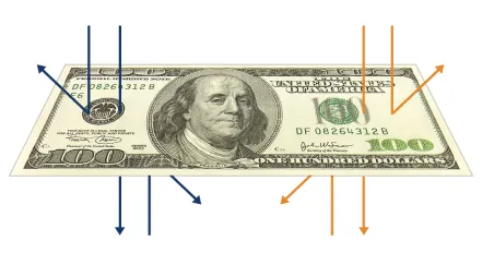
IR (Infra Red) Light Sensor
The IR (Infrared) Light Sensor captures banknote images using low-frequency light. Unlike visible light, which uses only reflected images, IR light is used to acquire both reflected and transmitted images.

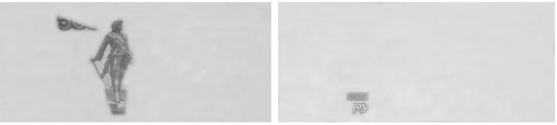
UV (Ultra Violet) Light Sensor
The UV (Ultraviolet) Light Sensor captures banknote images using high-frequency light. Genuine banknotes typically do not reflect UV light, whereas commonly used photocopied counterfeits do. Both reflected and transmitted images are analyzed.

Reflected and Penetrated Images
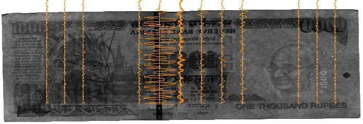
Magnetic Sensor
Banknotes are printed with magnetic inks in specific patterns. Magnetic sensors read these patterns to verify authenticity by detecting the presence, intensity, and spatial distribution of the magnetic signal across the note.
Two main sensor technologies are used in the industry: the MR Header (inductive magnetic head) and the MR Sensor (magnetoresistive sensor). With modern multi-channel MR Header modules now matching MR Sensor resolution, the choice between the two is primarily a matter of physical space rather than detection performance.
MR Header (Inductive Head)
Works on the same principle as a cassette tape pickup — electromagnetic induction. A separate magnet placed in front of the sensor magnetizes the banknote as it passes, and the sensor reads the resulting signal. Newer integrated modules based on TMR (Tunnel Magnetoresistance) now pack a magnet, multi-channel sensor array, amplifier, and ADC into a single package — offering up to 18 channels.
MR Sensor (Magnetoresistive)
A semiconductor-based sensor using the Hall effect / magnetoresistance. It directly senses the magnetic field without needing a separate magnet, and its output does not depend on how fast the banknote moves.
| Feature | MR Header | MR Sensor |
|---|---|---|
| Sensing principle | Electromagnetic induction | Magnetoresistance / Hall effect |
| Separate magnet needed | Yes | No |
| Speed dependent | Yes — signal varies with transport speed | No — constant signal regardless of speed |
| Typical channels | 1 (traditional); up to 18 (newer TMR modules) | 8–10 |
| SNR | Moderate | High |
| Relative cost | Lower | Higher |
| Form factor | Sensor + external magnet assembly | Compact single unit |
Why Resolution Matters
Many machines use a single-channel magnetic sensor that detects only the overall presence or absence of a magnetic signal. However, genuine banknotes have magnetic inks applied in precise patterns — certain areas must contain magnetic material while others must not.
A single channel cannot determine where across the note's width a signal originates. Multi-channel sensors scan the full width of the banknote, mapping the spatial distribution of the magnetic pattern. This allows significantly more precise counterfeit detection, because the sensor can verify not just whether magnetic material is present, but exactly where it appears.
Signal Comparison
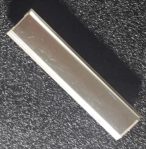
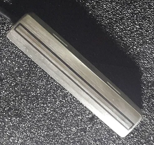
Physical Appearance
Converging Technologies
The boundary between these two technologies is blurring. Integrated MR Header modules based on TMR (Tunnel Magnetoresistance) technology now combine a magnet, sensor array, amplifier, and ADC in a single package — achieving up to 18 channels at 0.475 mm resolution. Meanwhile, MR Sensors continue to shrink in size. With multi-channel MR Headers now delivering resolution and SNR on par with MR Sensors, the primary trade-off is space: when the machine design allows room for the magnet assembly, the MR Header offers excellent performance at a lower cost; when the sensor area must be minimized, the MR Sensor's compact form factor is the better fit.
Tape Detection
Damaged banknotes are often repaired with adhesive tape. The tape may be transparent (scotch tape) or opaque — certain types, sometimes called "3M tape," appear opaque on their own but turn nearly transparent once pressed onto paper. Detecting these thin, often invisible layers is one of the most challenging tasks in banknote fitness sorting.
Traditionally, two approaches have been used: mechanical and ultrasonic thickness sensors. Both attempt to infer the presence of tape indirectly — by measuring a change in thickness or sound transmission. Each has significant limitations, which has driven the development of a fundamentally different approach: direct optical imaging.

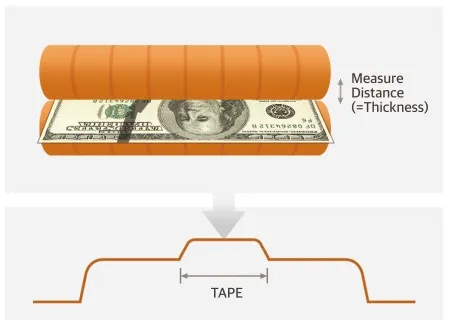
Mechanical Thickness Sensor
A spring-loaded probe presses against the banknote as it passes through the transport path. The deflection of the spring is converted into an electrical signal — either through an inductive (coil-based) or capacitive pickup — and amplified to estimate the paper thickness. A taped area is slightly thicker, producing a different reading.
The main weakness is mechanical in nature. Banknotes travel at high speed, and each note physically collides with the spring-loaded sensor. This causes the spring to oscillate, generating audible noise and vibration that introduces measurement error. Because the sensor cannot settle before the next note arrives, it often fails to resolve the very small thickness difference that tape adds — typically less than 50 micrometers. As a result, tape detection rates remain limited despite the sensor making direct physical contact.
Ultrasonic Sensor
An ultrasonic transmitter sends a short acoustic pulse through the banknote, and a receiver on the opposite side measures the signal that passes through. A single sheet of paper attenuates the ultrasonic energy significantly — only about 1% reaches the receiver. When tape is present, the additional layer changes the attenuation pattern, which the system interprets as a thickness anomaly.
Because there is no physical contact, the ultrasonic method is far quieter than the mechanical approach. However, it has its own set of challenges. Adjacent ultrasonic channels can interfere with each other, reducing accuracy. Some manufacturers address this by stacking two layers of ultrasonic sensor arrays, which increases cost and machine size. Additionally, ultrasonic propagation is affected by air pressure — machines operating at different altitudes may produce inconsistent results. Edge-side tape (tape applied along the narrow edges of a banknote) is also difficult to detect, as the sensor array typically covers only the flat face.
| Feature | Mechanical | Ultrasonic |
|---|---|---|
| Detection method | Physical contact — spring deflection | Sound transmission — attenuation measurement |
| Acoustic noise | High — audible clatter from spring oscillation | Low — no physical contact |
| Air pressure sensitivity | None | Significant — altitude affects results |
| Edge-side tape | Limited | Difficult to detect |
| Channel interference | Not applicable | Mutual interference between channels |
2-Pocket Fitness Sorters — Tape Detection Quality
CBRF Test (%)
Our current models (MIB-11, SB-3000, MIB-5000) all use the same mechanical tape detection module.
A New Approach: Direct Optical Imaging
Both mechanical and ultrasonic methods share a fundamental limitation: they detect tape indirectly, by inferring its presence from thickness or sound anomalies. A different approach is to image the tape directly.
A multi-mode Contact Image Sensor (CIS) captures the banknote at high resolution — over 1,500 pixels across — under multiple spectral bands (visible, IR, and UV). Transparent tape that is invisible to the naked eye becomes clearly visible when illuminated under specific wavelengths and captured at this resolution. Because the sensor scans the entire surface of the note optically, it is unaffected by air pressure, altitude, or edge-side tape placement. There are no moving parts, so no acoustic noise from collisions and no mechanical wear.
The challenge is computational: analyzing 15 high-resolution images per banknote at speeds of 1,000+ notes per minute requires significant processing power. This is where a dedicated NPU (Neural Processing Unit) becomes essential — running a trained deep-learning model that classifies each note as "with tape" or "without tape" regardless of tape type, size, or position. To learn more about this approach, see our Advanced CIS and AI Platform Overview pages.
Want to learn more about our sensor technology?
Contact Us